What are the measurands and functions of the ROMEG system?
The following measurands and functions are measured by the ROMEG system:
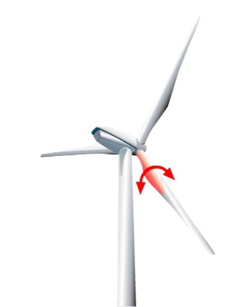
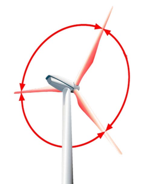
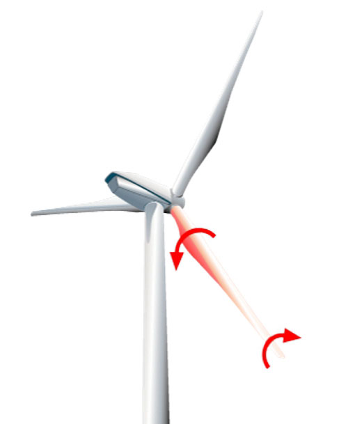
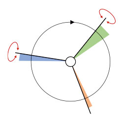
- Relative blade anglesl: The main function of the ROMEG system is to measure the relative blade angle deviation of the rotor blades, i.e. the angular deviation of the rotor blades from each other.
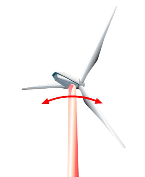
- Vibration analysis of the tower movement: The vibration pattern of the axial tower vibrations is a good indicator for the evaluation of the detected blade angle deviations .
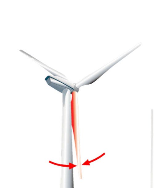
- Tower clearance
- Detection of mass imbalance

Measurands
Relative blade angles
When determining the relative leaf angles, the measured profile data are averaged leaf by leaf. The results represent the average values from the entire measurement period. It has been shown that a measurement period extending over 70 to 100 rotor revolutions provides a sufficiently large amount of data for a well-founded evaluation.
The averaged profile data of the rotor blades are compared and the geometric deviations are determined from the differences that occur.
Comparison measurements have shown that an accuracy of better than ± 0.15° is usually achieved in the area of the greatest profile depth.
Profile with blade angle deviation of 2.0°
Profile without blade angle deviation
Absolute blade angles
As a further service, we also offer the determination of absolute blade angles. Prerequisites for this are specific information from the manufacturer on the absolute blade angle and the availability of profile data of the rotor blade at the measuring point.
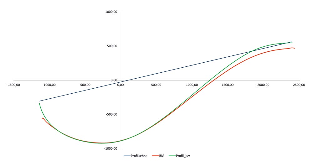
The deviation of the measured actual profile from the target profile is shown in the graphic.
This example shows a blade angle difference of 1.6°
Tower clearance
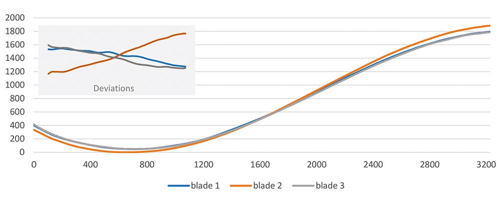
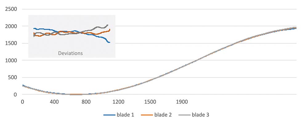
The information about the tower clearance of the blade tips is a revealing parameter for the evaluation of the blade behaviour in different load conditions.
In addition to the aerodynamic influences, the stiffnesses of the individual blades are also mapped in these measurements.
With the measurement of the tower clearance, the behaviour of the turbine can be mapped on several days in different wind situations, e.g. for special measurements.
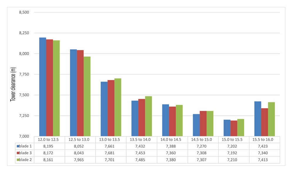
The upper graph shows the measurements of the tower clearance of the 3 blades over 100 rotor revolutions as well as the rotor speed.
Tower vibrations and vibration analysis
The vibration pattern of the axial tower vibrations is a good indicator for the evaluation of the detected blade angle deviations.
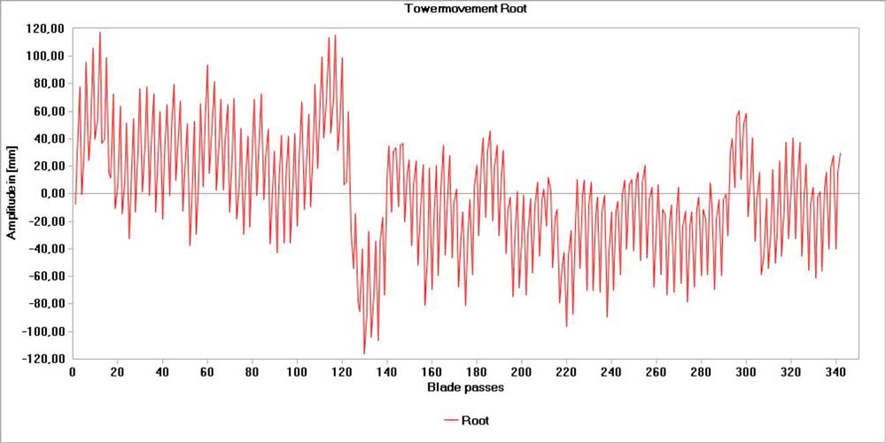
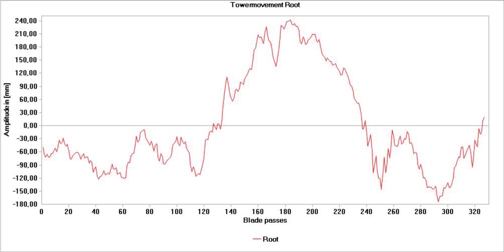
The graphs show the tower’s vibration behaviour before and after correction of the blade angles.
The significant decrease in the oscillation amplitudes due to the correction is clearly recognisable. With the decrease of the oscillation amplitudes, the damaging accelerations in the nacelle are considerably reduced.
Tower Movements with blade angle deviation of 2.0°
Tower Movements without blade angle deviation
In the vibration analysis, the time signal of the tower movement is broken down into its frequency components.
The stronger the unbalance, the stronger the excitation of the tower.
The FFT analysis is used to evaluate the strength of a detected unbalance in terms of relevance.
Tower vibrations with imbalance (FFT analysis)
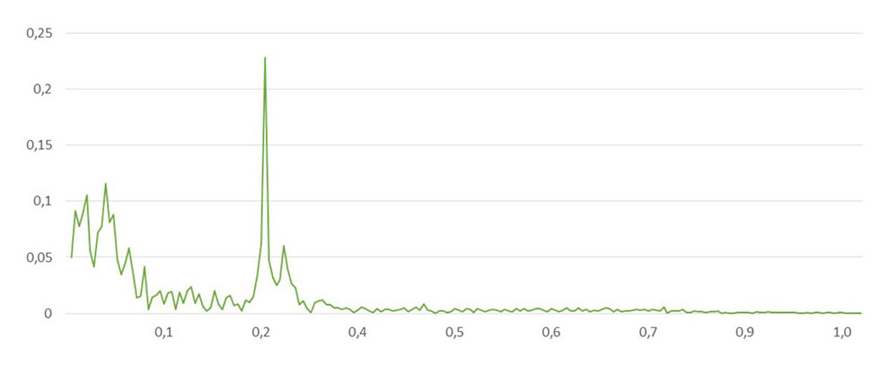
Strong excitation in the range of 1P
Tower vibrations without imbalance (FFT analysis)
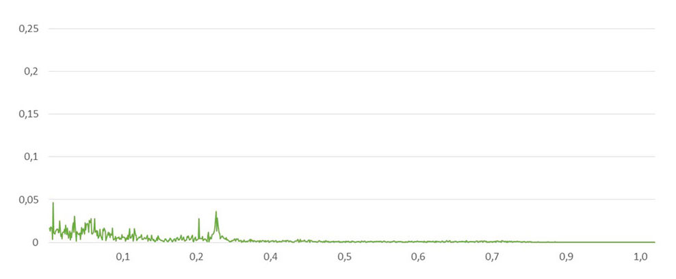
Weak excitation in the range of 1P
Detection of mass imbalance
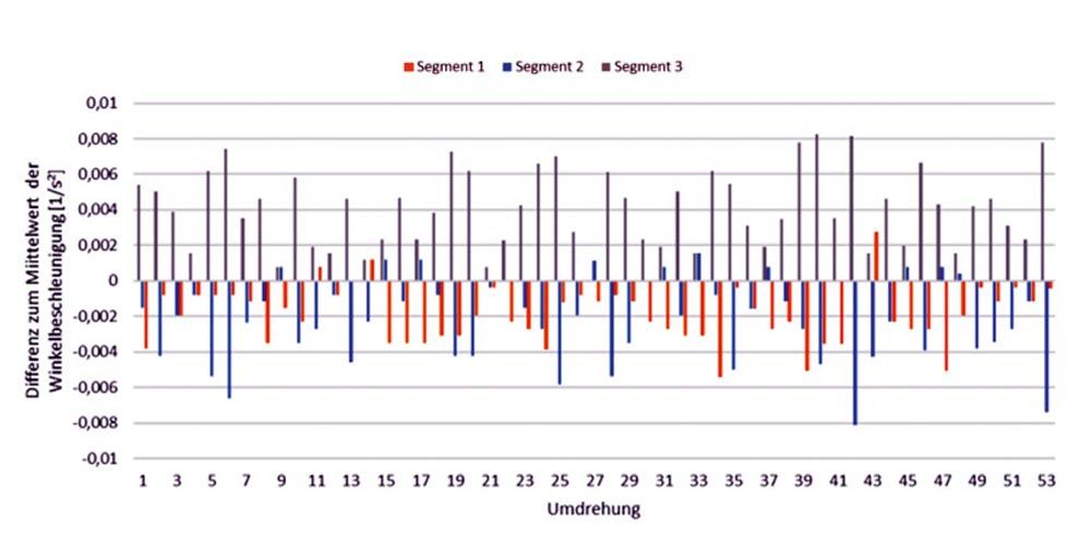
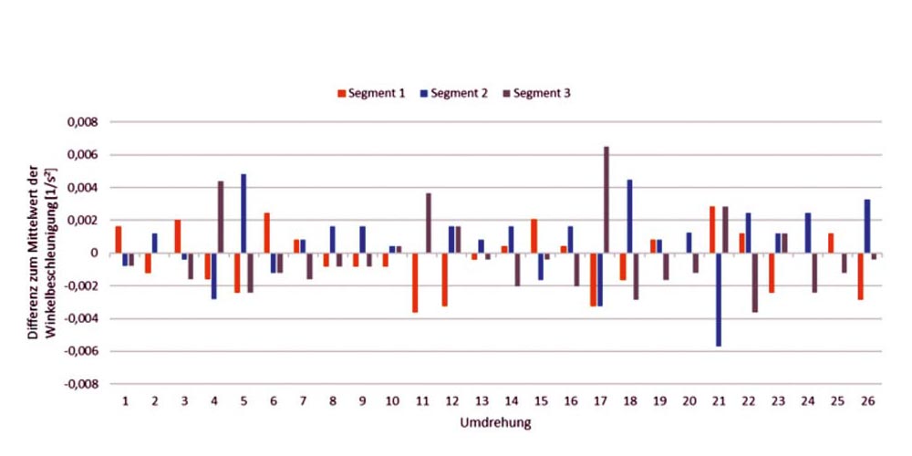
Mass differences in the rotor blades, i.e. an eccentric mass distribution in the rotor, generate a positive or negative acceleration in the course of rotation following the earth’s gravitational field, which can be detected by means of a high-resolution measurement.
In the case of mass imbalance, a characteristic distribution pattern appears over the entire measurement time. The affected rotor blade consistently shows an increased positive or negative acceleration.
In contrast, a characteristic distribution pattern is no longer recognisable in a measurement without mass imbalance.
Acceleration of the rotor with mass imbalance
Acceleration of the rotor without mass imbalance
Further topics
Here you can find more information about the ROMEG system.
What is the ROMEG-System?
With the ROMEG method, aerodynamically excited imbalances can be verified and mass-excited imbalances can be detected.
Setup of the ROMEG system
Learn more about the measurement setup of the ROMEG system, on- or offshore.

